Solve common or complex geotechnical challenges with PLAXIS
Award-winning software for design and analysis of soils, rocks, and associated structures
See all productsPLAXIS is trusted worldwide for reliable, risk-reducing geotechnical analysis.
Reliably solve infrastructure challenges
Easily generate and scale construction sequences for excavations of any complexity. Facilitate steady-state groundwater flow calculations, including flow-related material parameters, boundary conditions, drains, and wells.
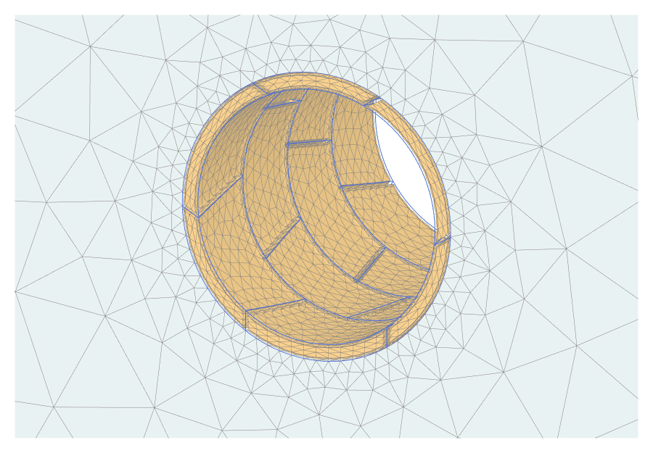
Use interfaces and embedded pile elements to model movement between soil and foundation, such as slipping and gapping.
Get trustworthy results with realistic soil models and a complete portfolio of visualisation abilities.
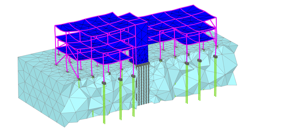
Create finite element models quickly and efficiently
Design and analyse soils, rocks, and associated structures in 2D or 3D. Drawing tools, such as extrude, intersect, combine, and array operations facilitate finite element modeling, while multicore calculations and a 64-bit kernel can handle simple and complex models. Create safer infrastructures with fully optimised designs.
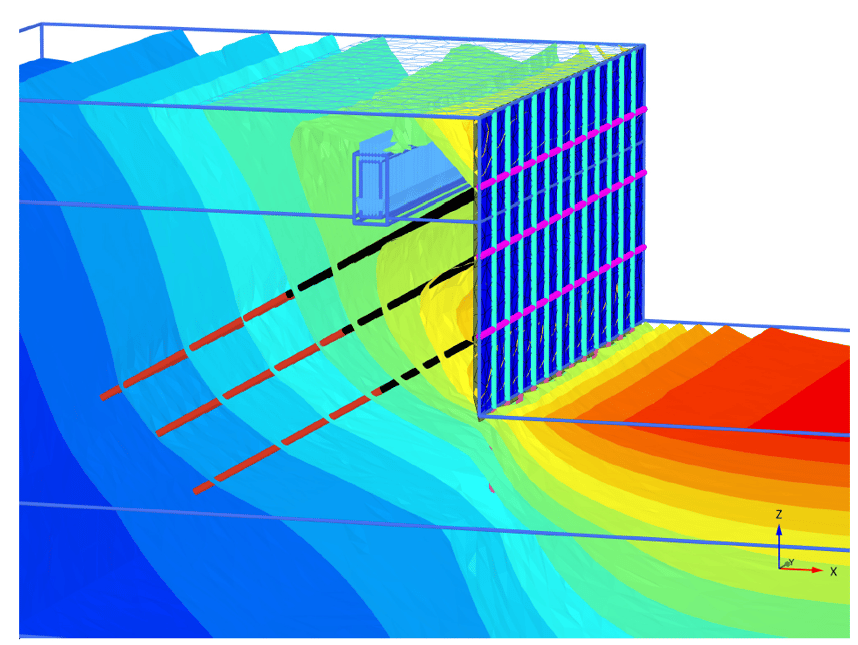
Get realistic assessments of stresses and displacements
To meet the unique geotechnical challenges of soil structure interactions, PLAXIS offers different calculation types, such as plastic, consolidation, and safety analysis. A range of material models for predicting the behaviour of various soils and rock types, combined with robust calculations, helps ensure reliable results. Display these forces in various ways and use cross-section applications to inspect certain areas in greater detail.
Explore PLAXIS
Whether you want to work in 2D or 3D, finite element or limit equilibrium,
there’s a PLAXIS option to help you conquer geotechnical challenges with confidence.
PLAXIS Monopile Designer
Monopile design software for reducing overall cost of wind farms.
Related Stories
See all
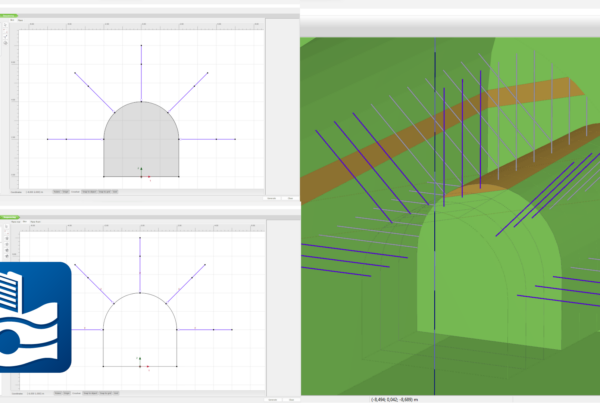
PLAXIS 2024.1 – What’s New
With PLAXIS 2024.1 users benefit from enhancements for designing and reinforcing underground excavations, improvement in…